
[UPDATED 5/28/2019 with BBadger’s most recent results and photos + 1/9/2022 with Brendan J’s feedback and photos]
I happened to see an interesting thread on the 124Spider forum that BBadger brought up, having to do with adding paddle shifters for those of us not owning the Abarth 124. I’ve already written about adding Sport mode (and it is looking promising), and now, the more I study the MX-5 Service Manual, adding paddle shifters looks equally promising, by simply ordering the parts from your Mopar parts source. Keep in mind though, that because the paddles are common across several Mazda models, they may be much easier (and cheaper; around $50) to obtain quickly through Mazda parts distributors, by ordering Mazda part numbers: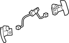
- N243663P0 for the paddles and wiring
- N24532750 for the set of (4) screws
- N2453204902 for the respective rear cover
Although the Info and Cruise Control switches are wired to the Start Stop module, apparently, the paddle shift wiring is missing from those same harnesses:
- From the paddle harness to the clock spring (3K (for ⇓), 3G (for ⇑) and 3I for ground), and needs to be added. See section First Missing Wiring Segment
- In addition, the paddle shift wiring is also missing from within the clock spring feeding the Start Stop unit 1N (for ⇓) and 1L (for ⇑) and bypass wiring from steering wheel clock spring (1D (for ⇓) and 1H (for ⇑) needs to be added, and this is done by modifying what Mazda calls “SHORT CORD” (Part # N256-67-SH0), one of 2 short harnesses that are taped together, connecting the clock spring to the front wiring harness behind, and from there to the Start Stop unit. The ground circuit (1F) should already be in place. Per BBadger, the tape wrapping the two harnesses needs to be cut, so that the short cord can be unplugged at both ends for removal and modification. See section Second Missing Wiring Segment

diagrams are courtesy of Mazda; click to enlarge

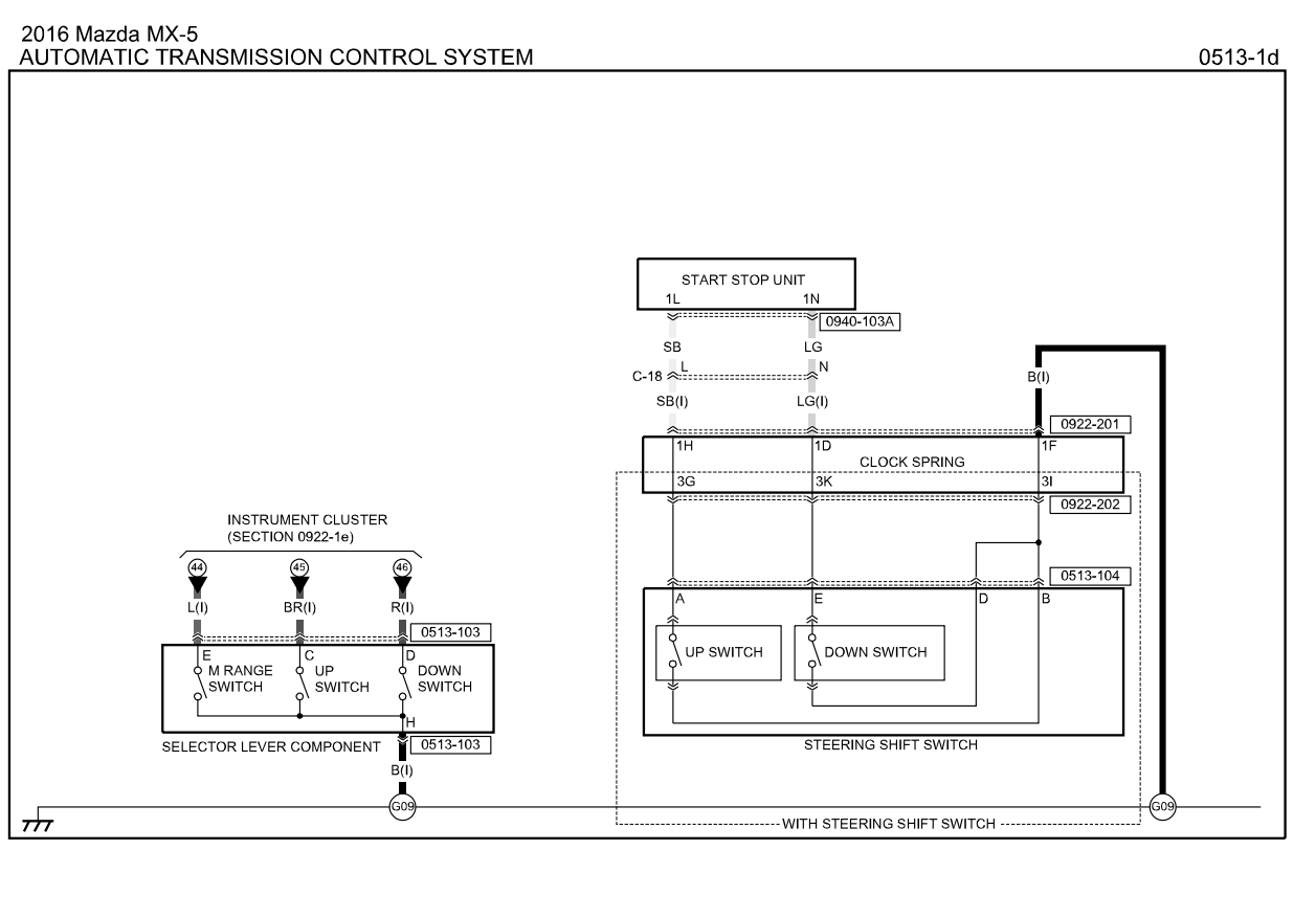


note the 3 empty terminal slots for the paddle shifter circuit
First Missing Wiring Segment
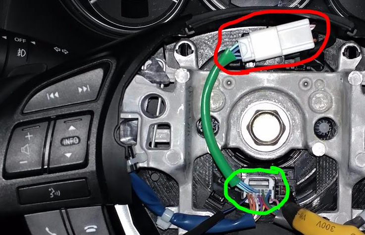
The first segment of missing wiring is the paddle shifter harness (shown as the green offshoot harness in the CX-5 photo below) will have to be addressed by one of the following options:
- wire the paddles to the 3 empty slots in the clockspring connector yourself (up, down and a shared ground)
- borrow the green offshoot from an upgraded steering wheel harness (Mazda # BNK8664M2) for the upgraded steering wheel wiring that plugs into the clock spring connector, to end up with the connector that the paddle shifter switches plug into (circled in red)
- remove the steering wheel switch pods and replace the entire steering wheel wiring harness with the new upgraded harness, which will then include the connector that the paddle shifter switches plug into (circled in red; if you choose this option, be sure to order the correct harness, ie. adaptive cruise requires yet a different part #)
⇓ Brendan J took this project on in December 2021, and chose to go with option #3 in his 2020 Lusso, stating:
I had to re-wire by hand the whole harness for the steering wheel controls.
I would have preferred to connect everything using butt connectors so that it would be easy to remedy incorrect connections, but since space is at a premium inside the steering wheel and I don’t have a soldering iron, I had to twist and heat shrink the wires together – securing it all with electrical tape to make sure everything stays in place.
Also, when removing the plastic trim on the steering wheel once you’ve got everything the horn/airbag assembly off, remove the black plastic rear cover FIRST. This exposes the back of the steering wheel where you can use a flat head screw driver to push the chrome trim/steering wheel control pods out and off of the steering wheel.
The black plastic rear cover is made of a very durable plastic, it is not likely to break. However, the plastic for the chrome pieces and the control pods is VERY BRITTLE, I broke 4 clips trying to figure out the most optimal procedure.
Finally, note the 14-pin-connector comparison I made in Photoshop. This may seem intuitive for some folks, but it took me some trial and error to figure out how to connect the new harness to everything. The new harness has the same 14-pin-connector as the OEM, thankfully, but unfortunately the OEM harness is hard wired/soldered to the steering wheel control pod circuit boards, making a simple “plug and play” solution impossible.

photo courtesy of Brendan J
Using the “diagram” above, it should be very easy, if not straight forward, to connect the new harness to the steering wheel control pods.
The only other issues I ran into were during the second half of the install, but those had more to do with the fact that there’s not a whole lot of space to work with under the driver-side dashboard and I’m not a small person to begin with.
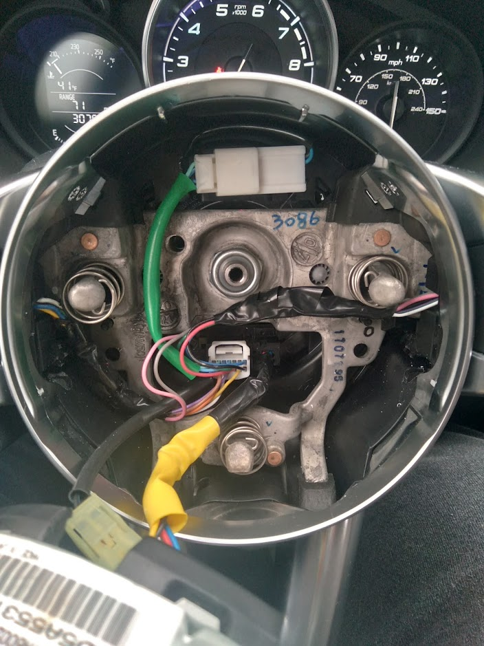
photo courtesy of Brendan J
Thank you for the additional info Brendan.
Second Missing Wiring Segment
The second segment of missing wiring is to the Start Stop unit from within the clock spring, and will have to be addressed by doing the following, per BBadger (he has a Classica, and although there is a small chance that the Lusso wiring may include this circuitry, at this point, we really doubt it):
The existing Short Cord (C-18) has all the wires. There must be a disconnect somewhere in the Start / Stop unit from the clock spring connector. You need to bypass this using the 3 pin wiring harness from Japan Parts (part # 479-006-003) (see IMG.3196__). They send out two versions, one with long pins and one with shorter pins. Use the longer pin one.
One end with the three pins goes into the three empty pin slots in the clock spring connector under the steering wheel (remove shroud to access) next to the yellow connector that connects to the airbag (IMG.3156__ and IMG.3205__ with green, black, and yellow inserted.) You will need to open the connector lock in order to insert the pins easily (IMG.3150__ shows this same connector unlocked under the airbag – easier to see here, note that the center section is raised (unlocked) slightly by about 1mm. You will need a small flat head screwdriver or pick to open. It runs across the middle of the connector on the bottom , pry up from each side. Reconnect this after you have the three wires installed and locked back down.
On the other end of the Japan Parts wiring harness, you connect a ring connector to the black wire. You will need to add in some extra wire to make it longer, I just used the red butt splice connector included with the part and 12” of extra black wire I had on hand. This gets grounded to the vehicle chassis (I drilled a hole into a bare metal area nearby and grounded it using a sheet metal screw [IMG.3248__]).
Cut off the pins on the yellow and green wires and crimp on the male T-Tap connectors. The reason I suggest using T-Taps – they allow you to disconnect the male from the female should you cross the wires – meaning that the Up Paddle Shift actually causes a downshift and vice versa. It is easy to correct with this type of connector just by switching the male connectors. On the removed Short Cord extension, carefully peel back the insulation so that you can tap into the light green and blue wires associated with 1L and 1N using the female T-Tap connectors (IMG.3230__, IMG.3238__, and IMG.3239__) and rewrap. Connect the male T-Taps into the females and reconnect the Short Cord connectors back into the receptacles under the dash.
Notes:
There is no need to insert pins into the 32 pin Short Cord connector, the pins / wires are already installed, just need to tap into the wires. You can see the two wires to tap into in the pic labeled (IMG.3167__).
Hover over these images for their file name, and click on those you wish to enlarge


this photo album, courtesy of BBadger

photo courtesy of Lamikeith
• N243663P0 for the paddles and wiring
• N24532750 for the set of (4) screws
• N2453204902 for the respective rear cover
• “SHORT CORD” (Part # N256-67-SH0)
• borrow the green offshoot from an upgraded steering wheel harness (Mazda # BNK8664M2)
• 3 pin wiring harness from Japan Parts (part # 479-006-003)
Yes, your parts list is accurate.
• For N24532750 you can use 10-32 1/2″ machine screws.
• I would also recommend buying a new steering wheel nut Mazda part# 999481200 rather than reusing the removed nut again.
• I ordered the “Short Cord” just to have on hand as insurance in case I damaged the original one when tapping into it or if I ever needed to remove the paddle shifts for re-sale of vehicle. Your call on that part.
• An automotive pin removal tool may also come in handy to scavenge the green offshoot from BNK8664M2. I was able to get the pins to release from the connector using a flattened out staple gun staple, but it would have been easier with the right tool.
Clock Spring
I found these videos to be educational regarding the clock spring, which contains a ribbon cable inside, rather than slip rings, which was the assumption I had made. There is a steering angle sensor that needs to be kept in mind, as everything goes back together, as well. Although it would seem logical that the clock spring units would be common for all MX-5 and 124 Spider variants, that turns out not to be the case, as BBadger found out.

Santtu has a manual shift Lusso, and had the idea to add paddle shifters, so that they could each trigger a cruise-control function as an alternative to the non-intuitive dedicated steering wheel switches. Seems like connecting the paddle switches so they tie into 1Y and 1Z on the Start Stop Unit, rather than 1L and 1N would do the trick, but it turns out to be impractical, since body ground isn’t involved, and you would have to introduce the correct resistor values as well. Otherwise, all the paddle switches would do is Cancel / Turn off the Cruise Control, rather than the desired Resume / + / Set / – functions.

Direct mode
When the steering shift switch is operated while driving with the selector lever in the D position, the gear position may temporarily switch. While in the direct mode, D and M illuminate in the indicator light and the operating gear position is displayed. The direct mode is canceled under the following conditions:
- Specified time has elapsed while driving at constant speed
- Vehicle stopped or driving at low speed
- Up switch for steering shift switch is pulled for certain period of time or more
♦♦♦

From the parts diagrams and description, it looks like in addition to the paddle shift switches and screws you will also need part# N2453204902 – REAR COVER w/SHIFT PADDLES. (the part picture mistakenly shows a front bezel).
LikeLiked by 1 person
Added to the article. Thanks, though it seems to me like the screws and cover should already be mounted to the un-paddled steering wheel.
LikeLike
I located a forum thread of someone adding paddle shifters to a Mazda 6 Touring steering wheel. It also required a new back cover, it has formed areas that hold the paddle shifters and the screws are used to secure them in place. The only question for me right now is if there is an pre-existing connector under the airbag for the paddle shift wiring. Will have to wait until spring to pop off the airbag and take a look. If not it would probably be pretty easy to wire up your own, or buy the one used in the Mazda install.
Here’s the thread:
https://forum.mazda6club.com/interior-exterior/410441-how-install-paddle-shifters-2016-touring.html
And a video from a Mazda 3 install:
LikeLiked by 1 person
Thanks for clearing up the need for screws and back cover.
Caught this in the thread:
Apparently, manual mode is temporarily engaged whenever the paddles are engaged while in automatic mode (Drive), reverting to automatic mode a short time after the paddles are no longer being used. The owner’s manual calls this Paddle mode, which is a nice feature! I’ve never driven a car with paddles, and I always assumed that the paddles were only available while in manual mode.
LikeLike
You can use the paddles if you’re in D. The car then switches to manual mode and stays there until you
– tell it to go back to D (pull the shift-up pedal for ~ 2secs or move the shift knob from D to manual and back)
– come to a halt.
Never observed that it will go back to D when you stop using the pedals.
LikeLike
Hmmm, OK. Per page 162 of the 2017 Abarth 124 Owner’s Manual:
That feature was praised on another Mazda thread, and that is where I learned about it first, before finding it in the manual. 😉
LikeLike
😀 So completely different from the German manual.
Just checked the Fiat eLum site for an English 2017 manual
source; page 115
Same description as in my German manual
P.162 there has just some maintenance checklists.
Maybe a difference between EU and NA market?
LikeLike
I use Lola’s paddles a lot (North America) and can confirm that the transmission returns to automatic mode shortly after the last paddle press. And that at times, the transmission won’t let you switch into gears that it doesn’t think you need to be in.
LikeLiked by 1 person
Thanks for the confirmation Lou. Hard to believe that it works differently in Europe. 😉
LikeLike
I have 2 questions,
a- it is necessary buy a rear cover of the steering, to set up the pads?
b- I have some experiences working in cars. Do you believe it is necessary to be assembly by a technician?
I really appreciate your comments.
Thanks Sergio.
LikeLike
Sergio,
a- According to BBadger:” the back cover has formed areas that hold the paddle shifters and the screws are used to secure them in place”, so apparently yes.
b- If you can follow instructions, especially regarding the airbag removal, it isn’t “necessary” that a technician do the work; that was just my observational opinion, in general.
LikeLike
Great Thanks, good information, please continue with your web. I like very much..
Thanks
Sergio
LikeLiked by 1 person
[disregard; turns out he was viewing connector incorrectly – see his update comment]
On my 2017 Classica the Start Stop Connector has open pin locations at 1L, 1J, and 1D which isn’t matching up with the 2016 Mazda MX5 diagram posted here. I made connections to 1L, and 1J but was only able to trigger the windshield wiper Mist function. I will trying moving the 1L wire over to 1D to see if that works. Other possibility is to move 1J to 1D.
I am trying to locate the 2017 Classica wiring manual to confirm what these pin locations control. It’s available from MOPAR but costs $100.
LikeLiked by 1 person
Hello from Germany,
I have the same problem, have you already found a solution?
Greetings Tommy
LikeLike
Hello Tommy.
Yes, I have sorted out the solution and tested the paddle shift function successfully. I had some free time this past weekend and gave it another go using the actual Fiat 124 Spider wiring diagram that showed connector orientations and wire colors. The solution involves using T-Taps to splice into the existing wiring on Mazda part # N256-67-SH0 described as “Short Connector”.
I will post some more pictures and more details once the http://www.124Spider.org forum is back up for posting. My suggestion to anyone attempting this will be to order an extra “Short Connector” to have on hand if you accidentally damage the original. Cost in USA from Real Mazda parts is $40.00 shipped – cheap insurance. My final step is to pull the steering wheel and replace the back cover and mount the switches permanently. Hopefully tomorrow.
LikeLiked by 1 person
Perfectly the cable is then simply under the steering wheel of this clock spring 3H + 3D to the start stop unit 1L + 1N?, what about the ground line 3F? Greetings Tommy
LikeLike
Tommy, I think you are correct, except the wiring diagram says 1H + 1D. BBadger has confirmed that the wiring for Fiat is exactly the same. 1F is already OK (ground).
LikeLiked by 1 person
BBadger, You stated on May 7th
What was the outcome of that?
LikeLike
[That was a mistake, Dan.]
Once I received the Fiat wiring diagrams that showed connector orientation, I realized that I had actually put the pins in open spots 1X and 1V on the connector. I thought I was looking at the mating side in the Mazda diagram. Once I realized I was looking at the pin insertion side I discovered my mistake and that the wires needed for paddle shift were already there in location 1L and 1N. They just needed to be tapped into. I removed the wires I had mistakenly placed, cut off the pins and added the male T-Taps to them.
LikeLiked by 1 person
ok, so you have not installed the new wiring harness?
LikeLike
Yes I have. Just responding to a question regarding a post I made on May 7th.
LikeLike
Uh ok 👍
LikeLike
You are a brave and lucky man!! Those could have been airbag pins, instead of windshield squirters 🙂
We thank you for seeing this through!
LikeLike
Everything airbag related is marked in yellow in some fashion thankfully. I stay away from touching anything yellow.
LikeLiked by 2 people
hello in the USA I still do not understand from where to where you have laid the cables, I correct that I put in the lower clock spring connector 3 cables in HFD and then the 2 cables N and L with T-taps to the plug Start stop Unit N and L attach? F on earth is clear Greetings Tommy
LikeLike
Yes, that’s correct
LikeLiked by 1 person
it is done, T. – piece soldered everything installed, works 👍
LikeLiked by 1 person
Good! Glad it worked for you as well. I am curious as to what model you have, a Classica or a Lusso? Wondering if anything different with a Lusso? Also, would be interested in how you soldered the connections if you have a picture.
LikeLike
I have a Lusso. Picture follows 🙂
LikeLike
FYI Tommy – the only way to add photo to comment, is to provide url. The img tag doesn’t seem to function.
LikeLike
I added a section to the article today regarding Santtu’s idea on adding paddle shifters to his MT Lusso, so that they could be used for cruise control functions. If my analysis of the wiring diagrams is correct, this would not be practical to implement though, as I explain…
LikeLike
[edited for clarity by ameridan]
Good morning to all of you owners of the fiat 124.
I [mounted on the steering wheel with paddles off of a 124 abarth as a substitute] on my 124 luxury model with automatic transmission.
Everything works, [except] the paddles [which is the reason I bought the steering wheel], Can you tell me where is the error?
Thank you,
antonio forcina
LikeLike
antonio, I assume you aren’t as fluent in english (italian is your language, no?), because you asked the same question on another Fiat forum, and we’ve all been trying to tell you that the answers are in this article, but perhaps Google translate doesn’t do the job well for you (I am the same way with Italian articles 😉 )
Perhaps a reader might respond in Italian to explain that the portion of the article entitled “Second Missing Wiring Segment” contains the probable clues you need to resolve getting your paddles working.
LikeLike
buongiorno a tutti e a te Ameridan , pensavo che bastasse solo il volante abart con palette !!! per la mia 124 lusso automatica . pensavo che qualche appassionato di 124 spider in altre parti del mondo avesse gia’ risolto il problema , ho’ capito che la soluzione e’ all’interno del vostro articolo , un sincero saluto
[good morning to you all and to you Ameridan, I thought that only the Abarth steering wheel with paddles was enough !!! for my 124 automatic luxury. I thought that some 124 spider enthusiasts in other parts of the world had already solved the problem, I understood that the solution is within your article, a sincere greeting]
LikeLike
There is finally a post from the salty character Kubicide who had claimed he had performed the mod without splicing wires. He gives a vague description of moving wires from one harness to another. I’m gathering that he means he removed the necessary wires from the SHORT CORD and installed them into the appropriate places in the lower clockspring connector, rather than running the bypass with wire splices. This might be a viable option provided one can do whatever is necessary for the shared ground for the paddles.
https://www.124spider.org/threads/adding-paddle-shifters-to-classica-lusso.32090/post-514042
LikeLike
I couldn’t find any harness that had the wires from the lower clock spring connector to the short cord. The short cord wires aren’t long enough to reach on their own. But, maybe I missed something along the way that Kubicide found? He never posted any pics or specifics. I know on the CX5 mod that you need the Japan Parts wires to make it work.
LikeLike
Does anyone have a link to a proper connector pin tool for this installation? And, does anyone have a link to good instructions for removing the steering wheel? Thanks.
LikeLike
I found this video helpful:
You only need to insert the tool a half inch or so to hit the release springs. Any further and you’ve missed it. Disconnect battery and then wait 10 minutes, then push the brake pedal before doing any airbag work.
LikeLike
Hi Dan, the link to Mazda’s procedure for this installation in your disclaimer seems to be dead
LikeLike
The author of the online manuals may have been asked to take them down. I just checked, and you can still install the manuals on your PC as an offline version ~ see my article for the link: https://21stcenturyfiat124spider.wordpress.com/2016/10/29/html-version-of-service-manual/
I’ve also updated the links to the online manuals to a new currently-functioning source.
LikeLike
I updated the link to one that currently functions.
LikeLike
I added feedback comments and photos from Brendan J today, as he took this project on last month in his 2020 Lusso.
LikeLike
I just installed the paddles and they work! I’m not sure how responsive they are as the shifts seem delayed from when I press the paddle. I am also wondering how to check that the ground is done properly? I have a multimeter but I have no idea how to use it in the interior of the vehicle.
Any help is appreciated!
LikeLike