
factory Bose door speaker; photo courtesy of mgineering

non-Bose door woofer only weighs 10.6 oz! ~ photo courtesy of King-of-Hyrule
Like the MX-5, the Fiat 124 Spider audio system includes:
- one Mazda 6½” woofer in each door with custom mounting configuration
- one 1″ Mazda tweeter (with inline capacitor as crossover) in each A-pillar
- one pair of 2″ speakers in the driver’s seat headrest

Headrest speakers with seat cover and styrofoam headrest filler removed (see this thread if you hear distortion)
…and, if you have the Bose® system:
- Bose® branded versions of all aforementioned speakers that are a different impedence
- another pair of 2″ Bose® branded speakers in the passenger-seat headrest
- one Bose® 5¼” custom “sub-woofer” module contained in a cavity beneath the footrest wedge in the passenger-side foot well (see my other blog article for more on replacing this module)
There is an excellent write-up on “upgrading” the Bose® speakers in the MX-5 with JBL GX600C speakers in the Miata.net forum. This is not a project I intend to take on, nor do I have the Bose® system in my Classica, but seeing mention of:
- some nice MJM door speaker adapters that allow you to easily mount aftermarket 6½” woofers in place of the Mazda mounted woofers
- and Metra speaker harness adapters, so that no wiring cutting/twisting/soldering is required
…I felt it warranted a short article to save any 124 owners wanting to replace their door speakers, a lot of aggravation and research. Others have reported great success with JBL GTO629 and JBL GX602 speakers. not sure just replaced his factory door speakers with Polk Audio DB6502, 300 watt speakers and he’s very happy with the results too (according to Crutchfield, you should look for woofers with a mounting depth not exceeding 2.511 inches). rsmagee noted that the wiring harness orientation should remain intact, so as not to divert rain water passing through the door onto the trim panel (and from there, into the vehicle). Due to gram strategy, there are no water shields within the doors.
I’ve come across another article by Mark Rivera (Paco Motorsports; they also sell audio harnesses and upgrade kits) on upgrading the Bose setup in particular, that you may find very informative.
NOTE: Since the mounting configuration of non-Bose factory woofers (door speakers) is identical, these adapters are reported to work well in accommodating aftermarket replacement speakers for them as well.

MJM adapters – model SAK 112
Description:
- Allows you to replace factory speakers with aftermarket speakers
- Made in the USA by car-speaker-adapters.com
- Guaranteed not to rattle
- PVC is tough as nails
- CNC machined adapters ensure an accurate fit
- Will not rot like MDF or wood speaker mounts
- Makes speaker installation a snap
- Designed to fit vehicle(s) listed below perfectly, not a universal speaker bracket
- Acts as a spacer in addition to being an adapter
- A hassle free alternative to making your own speaker baffles
- An asset when installing automotive speakers
- Allows use of factory speaker grills to ensure OEM appearance
- Backed by a 100 percent satisfaction, money back guarantee
- Includes 2 adapters plus hardware
- Priced per pair
- 3/4” deep adapters assure no clearance problems
- Utilizes existing vehicle mounting points, and requires no cutting or drilling
- Made with 5 1/2″ round cutouts to house most 6 1/2″ aftermarket speakers
Adapter Kit Fits:
2017+ Fiat & Abarth 124 Spider Front Location (added by me)

replaced speaker; photo courtesy of mgineering
Speaker Impedance Values:
- Door speakers
→ →Without Bose: 3.4—4.6 ohms
→ →With Bose: approx. 2.1 ohms - Headrest speakers
→ →Without Bose: 3.4—4.6 ohms
→ →With Bose: approx. 4.0 ohms
(if you install Bose equipped seats in a non-Bose vehicle, by tapping into the driver’s seat wiring meaning both seats are wired in “parallel”, the impedance will drop from 4.0 ohms to 2.0 ohms which will produce a higher level of sound in the seat speakers) - Tweeters
→ →Without Bose: 3.4—4.6 ohms
→ →With Bose: 3.06—4.74 ohms - Sub-woofer
→ →Approx. 1 ohm
Gerry has done a nice write-up (with photos) on replacing all of the Bose speakers in the MX-5, which might prove useful to anyone considering doing so. Other than the door trim panel, all of the instructions should be applicable to the Fiat 124. Regarding the door trim panel…
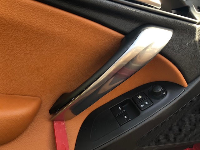
Door trim panel removal instructions (thanks to softailfxstd and pics by King of Hyrule):
Removal time about 5 minutes…..
1. Using a plastic tool trim tool, pop off the small plastic panel behind the lock/unlock lever exposing the first of 3 screws holding the trim panel to the door frame.
2. Remove that screw
3. Using a plastic trim tool, pop off the silver door handle cover to expose two screws (I used a plastic hook tool starting at the lower part of the handle)
4. Remove the last two screws now exposed (no need to separate handle from the door panel)all three screws that need to be removed are visible
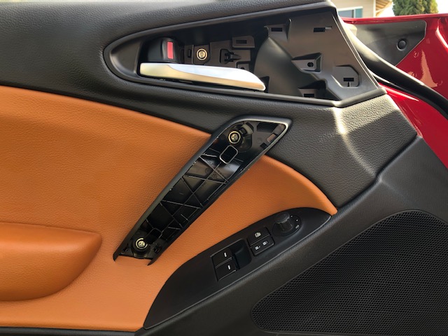
5. Starting at the bottom of the door panel using a trim tool, gently detach the panel away from the frame
6. Use the trim tool to disconnect the white plastic push fasteners located around the perimeter of the panel
7. Note the rubber gasket does not need to be removed.
8. The panel is now free to be lifted upward and away from the door frame
9. Disconnect the door speaker harness, window switch harness, and door lock switch harness
10. Remove the door lock lever assembly by turning it from the rectangular opening
MX-5 INFOTAINMENT SYSTEM [CMU]
(extracted from the Mazda Service Manual for informational purposes only)
System Schematic Diagram

Structural View

System diagrams
⇓ Without Bose®

⇓ With Bose®


courtesy of Mark Rivera; he added notes and wire colors/polarity to the low-level signals you can intercept in the passenger rocker area if you want to run dedicated amps, DSP, etc…
The following is courtesy of poxin, who also took this project on, and located a source for a wiring harness, so he wouldn’t have to splice into any factory wiring…


Wiring Colors

Operation
Operation signal reception
- Each function of the entertainment system operates if any of the operations in the following table is performed.
- × = Operates
- — = Does not operate
| Function | Center display operation (touch position signal) | Commander switch operation | Voice recognition function operation (steering switch operation and audio signal (voice command)) | |
| Audio function | AM/FM radio | × | × | × |
| HD radio™ | × | × | × | |
| SiriusXM satellite radio | × | × | × | |
| Aha™ radio Pandora® Stitcher™ radio |
× | × | × | |
| AUX/USB audio | × | × | × | |
| Bluetooth® audio | × | × | × | |
| CD playback | × | × | × | |
| Centerpoint®*9 | — | — | — | |
| Communication function | SMS (Short Message Service) | × | × | × |
| Bluetooth® (Hands-Free) function | × | × | × | |
| Mobile 911 | × | × | — | |
| Navigation function | Map display, route guidance | × | × | × |
| Setting function | Bluetooth® pairing | × | × | — |
| System setting | × | × | — | |
| Screen setting | × | × | — | |
| Sound setting | × | × | — | |
| Clock setting | × | × | — | |
| Personalization feature setting | × | × | — | |
| Application function | Fuel economy monitor | × | × | — |
| Maintenance monitor | × | × | — | |
| Warning guidance | × | × | — | |
- *9
- If the Centerpoint® setting is on, it operates automatically even if the user does not perform any operations. The Centerpoint® on/off setting can be changed by operating the center display and commander switch.
Operation signal reception from center display
- When the center display is operated, the center display detects (1) the touch position.
- The center display sends (2) a touch position signal (LVDS*10 signal) to the CMU based on the detected touch position.
- The CMU sends (3) the control signal to the related units based on the received touch position signal.
- *10
- The LVDS displays the electrical properties of the signal using low-voltage differential signaling. LVDS is a digital, wired transmission technology for the short range which adopts a differential interface having the characteristics of low voltage and low power consumption.

Operation signal reception from commander switch
- When the commander switch is operated, the CMU detects (1) the commander switch operation.
- The CMU sends (2) the display signal (LVDS signal) to the center display based on the detected commander switch operation. In addition, it sends (2) a control signal to the related units.

Operation signal reception from voice recognition function
- When the talk button on the steering switch is pressed, the CMU detects (1) the steering switch operation.
- When the CMU detects the steering switch operation, it sends (2) a guidance audio signal to the tuner and amplifier unit (TAU).
- The TAU sends (3) the guidance audio signal to the speakers and the speakers output (3) the guidance audio.
- The voice recognition-use microphone converts the words (voice commands) produced by the user after the guidance audio output to an audio signal and sends it to the CMU.
- The CMU sends (5) the control signal to the related parts based on the audio signal received from the voice recognition microphone.

Audio function
AM/FM radio
- When the CMU receives the operation signal/detects the switch operation, it sends (1) the control signal to the TAU.
- When the TAU receives the control signal, it switches (2) the tuner inside the TAU to radio mode and initiates reception of radio broadcasts.
- The TAU detects the radio broadcast selected by the user using the tuner in the TAU based on the electrical signal received (3) from the rod antenna The audio signal of the detected radio broadcast is sent (3) to the speakers. In addition, the frequency of the detected radio broadcast is sent to the CMU.
- The CMU converts the radio broadcast received from the TAU to a LVDS signal and sends (4) the LVDS signal to the center display.
- The speakers output (5) the audio based on the audio signal sent from the TAU. In addition, the center display indicates (5) radio information based on the LVDS signal.

Radio broadcast data system (RBDS)
- When the CMU receives the operation signal/detects the switch operation, it sends (1) the control signal to the TAU.
- When the TAU receives (2) the control signal, it starts RBDS reception.
- The rod antenna sends the received (3) RBDS information (electrical signal) to the TAU.
- The TAU sends text information to the CMU based on the received RBDS information. In addition, it sends (4) the audio signal to the speakers.
- The CMU converts the received (5) text information to a LVDS signal and sends it to the center display.
- The center display (6) indicates the RBDS information based on the received LVDS signal. In addition, the speakers output (6) the audio based on the received audio signal.

RBDS-TMC
- The rod antenna converts the radio waves to an electric signal and sends (1) it to the TAU.
- When RBDS data from the electric signal is detected, the TAU converts information such as radio station name and song information to a RS485 signal and sends (2) the converted RS485*11 signal to the CMU.
- The CMU converts the text information received (3) from the TAU to a LVDS signal and sends the LVDS signal to the center display.
- Based on the received LVDS signal, the center display indicates (4) traffic information such as the location and distance of traffic jam.
- *11
- RS485 corresponds to a linear, multi-drop configuration with bi-directional transmission, which is one of the possible types of serial communication standards, having a maximum transmission speed of 10 Mbps.
HD radio™
- When the CMU receives the operation signal/detects the switch operation, is sends (1) the control signal to the TAU.
- When the TAU receives the control signal, it switches (2) the tuner in the TAU to radio mode and initiates reception of the radio broadcast.
- The TAU detects the radio broadcast of the radio station selected by the user using the tuner in the TAU based on the electrical signal received (3) from the rod antenna. The audio signal of the detected radio broadcast is sent to the speakers. In addition, the detected radio broadcast logo or album is converted to a RS485 signal and the signal is sent (3) to the CMU.
- The CMU converts the RS485 signal from the TAU to a LVDS signal and sends (4) the LVDS signal to the center display.
- The speakers output the audio based on the audio signal received (5) from the TAU. In addition, the center display indicates (5) HD radio information based on the LVDS signal.

SiriusXM satellite radio
- When the CMU receives the operation signal/detects the switch operation, it sends (1) the control signal to the TAU.
- When the TAU receives the control signal, it switches (2) the tuner inside the TAU to SiriusXM satellite radio mode and initiates reception of radio broadcasts.
- The TAU detects the radio broadcast selected by the user using the tuner in the TAU based on the electrical signal received (3) from the SiriusXM satellite radio antenna. The audio signal of the detected radio broadcast is sent to the speakers. In addition, the detected radio broadcast information is sent (3) to the CMU.
- The CMU converts the radio broadcast information received from the TAU to a LVDS signal and sends (4) the LVDS signal to the center display.
- The speakers output (5) the audio based on the audio signal received from the TAU. In addition, the center display indicates (5) SiriusXM satellite radio information based on the LVDS signal.
Aha™ radio/Pandora®/Stitcher™ radio
- When the CMU receives the operation signal/detects the switch operation, it sends (1) the control signal to the TAU and a mobile device such as a Bluetooth®-enabled mobile phone or a Smartphone.
- When the mobile device such as a Bluetooth®-enabled mobile phone or a Smartphone receives the control signal, it receives the Aha™radio/Pandora®/Stitcher™ radio and sends (2) the digital data to the CMU.
- The CMU converts the received video signal of the digital data to a LVDS signal and sends (3) the LVDS signal to the center display. In addition, it sends (3) the audio signal to the TAU.
- The center display indicates (4) the radio information based on the LVDS signal received from the CMU. In addition, the TAU sends (4) the received audio signal to the speakers. The speakers output (4) the audio based on the received audio signal.

AUX
- When the CMU receives the operation signal/detects the switch operation, it sends (1) the control signal to the TAU.
- The TAU sends (2) the received (2) audio signal to the speakers and the speakers output (2) the audio based on the received audio signal.

USB audio
- When the CMU receives the operation signal/detects the switch operation, it sends (1) the control signal to the TAU.
- The auxiliary jack/USB port/SD card slot hub sends (2) the digital data (audio signal/music information such as album name or artist name) of the USB device/iPod connected to the USB port to the CMU.
- The CMU transmits (3) the received audio signal to the TAU, converts music information to a LVDS signal, and sends (3) it to the center display.
- The center display indicates (4) the music information based on the LVDS signal received from the CMU. In addition, the TAU sends (4) the received audio signal to the speakers and the speakers output (4) the audio based on the received audio signal.

Bluetooth® audio function
- When the CMU receives the operation signal/detects the switch operation, it sends (1) the control signal to the TAU and a mobile device such as a Bluetooth®-enabled mobile phone or a Smartphone.
- When the mobile device such as a Smartphone or a Bluetooth®-enabled device receives the control signal, the digital data is sent (2) to the CMU.
- The CMU converts the video signal of the digital data to a LVDS signal and sends (3) it to the center display. In addition, it sends (3) the audio signal to the TAU.
- The TAU sends (4) the received audio signal to the speakers.
- In addition, the center display indicates (5) Bluetooth® audio information based on the LVDS signal. In addition, the speakers output (5) the audio based on the received audio signal.

CD playback
- When the CMU receives the operation signal/detects the switch operation, it sends (1) the control signal to the TAU. In addition, the control signal is sent (1) to the CD player.
- When the CD player receives the control signal, it sends (2) music information such as the album name and artist name of the inserted CD to the CMU, and it sends (2) the audio signal to the TAU.
- The CMU converts the received music information signal to a LVDS signal and sends (3) it to the center display. The TAU sends (3) the received audio signal to the speakers.
- The center display indicates (4) the music information signal based on the LVDS signal. In addition, the speakers output (4) the audio based on the received audio signal.

Gracenote updating
- The auxiliary jack/USB port/SD card slot hub sends (1) the Gracenote update information on the USB device.
- The CMU verifies the Gracenote update information received from the auxiliary jack/USB port/SD card slot hub and performs (2) the update.

Communication function
SMS (Short Message Service)
- When the CMU receives the operation signal/detects the switch operation, is sends (1) a control signal to a mobile device such as a Bluetooth®-enabled mobile phone or a Smartphone.
- When the mobile device such as a Smartphone or a Bluetooth®-enabled device receives the control signal, the digital data is sent (2) to the CMU.
- The CMU converts the video signal of the digital data to a LVDS signal and sends (3) the LVDS signal to the center display.
- The center display indicates the SMS information based on the received LVDS signal.

Bluetooth® (Hands-Free) function (incoming calls)
- When an incoming call is received, a mobile device such as a Bluetooth®-enabled mobile phone or a Smartphone sends (1) the incoming call signal to the CMU.
- When the CMU receives the incoming call signal, it sends (2) the incoming call pop-up screen display signal (LVDS signal) to the center display.
- When the center display receives the incoming call pop-up screen display signal (LVDS signal), it displays (3) the incoming call pop-up screen.
- If the pick-up button on the steering switch is pressed while the incoming call pop-up screen is displayed, the CMU detects (4) the steering switch operation.
- When the CMU detects the steering switch operation, it sends (5) the call answer signal to a mobile device such as a Bluetooth®-enabled mobile phone or a Smartphone, and the call is initiated.
- The mobile device, such as a Bluetooth®-enabled mobile phone or a Smartphone, sends (6) the received audio signal to the CMU, and the signal is output (6) from the speakers via the TAU.
- The voice recognition-use microphone sends the send audio signal of the user to the CMU, and the CMU sends (7) the received send audio signal to a mobile device such as a Bluetooth®-enabled mobile phone or a Smartphone.
NOTE:
- When the call initiates, the incoming call pop-up screen switches to the call screen.

Bluetooth® (Hands-Free) function (outgoing calls)
- When the talk button on the steering switch is pressed, the CMU detects (1) the steering switch operation.
- When the CMU detects the steering switch operation, it sends (2) a guidance audio signal to the TAU.
- The TAU sends (3) the guidance audio signal to the speakers and the speakers output (3) the guidance audio.
- The voice recognition-use microphone converts the words (voice commands) produced by the user after the guidance audio output to an audio signal and sends it to the CMU.
- When the CMU receives the audio signal from the voice recognition-use microphone, it sends (5) an outgoing call signal to a mobile device such as a Bluetooth®-enabled mobile phone or a Smartphone, and the call is initiated.
- The mobile device, such as a Bluetooth®-enabled mobile phone or a Smartphone, sends (6) the received audio signal to the CMU, and the signal is output (6) from the speakers via the TAU.
- The voice recognition-use microphone sends the send audio signal of the user to the CMU, and the CMU sends (7) the received send audio signal to a mobile device such as a Bluetooth®-enabled mobile phone or a Smartphone.

Mobile 911 (Auto outgoing call performed)
- When an accident occurs under specified conditions, the SAS control module sends a fuel cut request signal to the CMU.
- When the CMU receives the fuel cut request signal from the SAS control module, it sends the guidance audio signal to the TAU. In addition, it sends the Mobile 911 screen display signal (LVDS signal) to the center display.
- The TAU sends the guidance audio signal to the speakers and the speakers output the guidance audio. In addition, the center display displays the Mobile 911 screen.
- The CMU executes the 10 s timer after the guidance audio output.
- After 10 s have elapsed on the timer, the CMU sends an outgoing call signal to a mobile device such as a Bluetooth® enabled mobile phone or a Smartphone.
- When the mobile device, such as a Bluetooth®-enabled mobile phone or a Smartphone, receives the outgoing call signal, it calls the PSAP (Public Safety Answering Point).
- After connecting to the PSAP (Public Safety Answering Point), the CMU outputs the vehicle position information from the vehicle speakers and initiates the call.
Mobile 911 (auto outgoing call canceled)
- When the SAS control module operates the air bags, a fuel cut request signal is sent to the CMU.
- When the CMU receives the fuel cut request signal from the SAS control module, it sends the guidance audio signal to the TAU. In addition, it sends the Mobile 911 screen display signal (LVDS signal) to the center display.
- The TAU sends the guidance audio signal to the speakers and the speakers output the guidance audio. In addition, the center display displays the Mobile 911 screen.
- The CMU executes the 10 s timer after the guidance audio output.
- If the Cancel Call to 911 operator is selected on the center display/Hang-up button on the steering switch is pressed while the timer executes the 10 s timer, the center display/steering switch sends a cancel signal to the CMU.
- When the CMU receives the cancel signal, it stops the 10 s timer and cancels the auto outgoing call to the PSAP (Public Safety Answering Point).

Navigation function
Map display, route guidance
- When the CMU receives the operation signal/detects the switch operation, it sends (1) the control signal to the TAU.
- The CMU reads (2) the map information of the SD card inserted in the auxiliary jack/USB port/SD card slot hub. In addition, reception of the position information from the GPS antenna is initiated.
- The CMU sends (3) the navigation screen display signal (LVDS signal) to the center display based on the SD card map information and the position information from the GPS antenna.
- The center display displays (4) the navigation screen based on the received navigation screen display signal (LVDS signal).
- The CMU detects (5) the route to the destination set by the user and sends (5) the guidance audio signal to the TAU after deciding the route.
- The TAU sends (6) the guidance audio signal to the speakers and the speakers output (6) the guidance audio.

Setting function
Bluetooth® pairing
- When the CMU receives the operation signal/detects the switch operation, it transmits a search signal to a Bluetooth® enabled device near the CMU and sends (1) the Bluetooth®-device search screen signal to the center display.
- The Bluetooth®-enabled device near the CMU sends (2) a Bluetooth® device signal to the CMU. In addition, the center display displays (2) the Bluetooth® device search screen.
- The CMU programs (3) the Bluetooth®-enabled device information based on the Bluetooth® device signal.
NOTE:
In the following cases, Bluetooth® pairing is canceled.
- Eight (maximum of 7) Bluetooth® devices have been programmed
- Bluetooth® device signal is not received during period of 180 s
- Cancel is selected during Bluetooth® device search screen display

System/screen/clock settings
- When the ACU receives the operation signal/detects (1) the switch operation, it changes (1) each function setting based on the information from the user operations.

Sound setting (sound quality setting/volume setting)
- When an operation signal is received/switch operation is detected (1), the CMU sends (1) a sound setting information signal to the TAU based on the information from the user operations.
- The TAU changes (2) the setting value for each function based on the received sound setting information signal.

Personalization feature setting
- When an operation signal is received/switch operation is detected (1), the CMU sends (1) a personalization operation signal to the related units based on the personalization setting information set by the user.
- The related unit changes (2) each function setting based on the personalization operation signal.

Important: Ignition switch must be ON (not Accessory mode) in order to change vehicle settings ⇒ from the Home screen, select the Settings icon to proceed…

♦♦♦♦ bold entries are my additions and corrections ♦♦♦♦

♦♦♦♦ note: All doors includes fuel filler door ♦♦♦♦

some regions also allow for turning DRL off

TUNER AND AMP UNIT [WITH CENTER DISPLAY]
Purpose
- Controls the audio signal from the entertainment system-related parts.
Function
Tuner switching function
- The tuner and amplifier unit (TAU) switches the tuner mode built-into the TAU based on the control signal sent from the connectivity master unit (CMU).
Audio signal output function
The TAU outputs the audio signal sent from the following units to the speakers.
- CMU
- CD player
- Auxiliary jack/USB port/SD card slot hub (only auxiliary jack)
RS485*1 signal conversion function
NOTE:
The RS485*1 signal wiring harness is used in the following cases:
HD radio™
- Radio broadcast logo, album art, or song name is sent to CMU from TAU
RBDS-TMC
- Traffic information such as location and length of traffic jams is sent to CMU from TAU
- The TAU creates data from the radio waves received from the antenna and converts the created data to a RS485 signal and sends it to the CMU.
- *1
- RS485 corresponds to a linear, multi-drop configuration with bi-directional transmission, which is one of the possible types of serial communication, having a maximum transmission speed of 10 Mbps.
ALC (auto level control) function
- When the TAU receives the vehicle speed signal sent from the instrument cluster, it automatically changes the volume and audio quality according to the vehicle speed and compensates for the passengers’ sense of a lack of audio volume which occurs as a result of external noise while driving.
Specification
| Item | Specification | |
| Rated voltage | 12 volts | |
| Frequency range | AM | 530—1710 kHz |
| FM | 87.75—107.9 MHz | |
| Amplifier maximum output | with Bose®: 281 watts without Bose®: 25×4 watts |
|
| Output impedance | 4 ohms | |
Construction
- The TAU unit is located in the upper part of the front side trim (RH).
Input/output signal table
| Terminal | Signal | |
|
|
1A | — |
| 1B | — | |
| 1C | — | |
| 1D | — | |
| 1E | — | |
| 1F | — | |
| 1G | — | |
| 1H | — | |
| 1I | AUX audio input LH (+) | |
| 1J | AUX audio input LH/RH (-) | |
| 1K | AUX audio input RH (+) | |
| 1L | AUX connection detection | |
| 1M | CD audio input LH (+) | |
| 1N | CD audio input LH (-) | |
| 1O | CD audio input RH (+) | |
| 1P | CD audio input RH (-) | |
| 1Q | CMU audio input LH (+) | |
| 1R | CMU audio input LH (-) | |
| 1S | CMU audio input RH (+) | |
| 1T | CMU audio input RH (-) | |
| 1U | — | |
| 1V | — | |
| 1W | RS485 signal (+) | |
| 1X | RS485 signal (-) | |
|
|
2A | Without Bose® : Door speaker/tweeter output LH (+)
With Bose® : Front speaker output LH (+) |
| 2B | B+ | |
| 2C | Without Bose® : Door speaker/tweeter output LH (-)
With Bose® : Front speaker output LH (-) |
|
| 2D | Without Bose® : Door speaker/tweeter output RH (+)
With Bose® : Front speaker output RH (+) |
|
| 2E | — | |
| 2F | Without Bose® : Door speaker/tweeter output RH (-)
With Bose® : Front speaker output RH (-) |
|
| 2G | — | |
| 2H | Without Bose® : —*2
With Bose® : — |
|
| 2I | Without Bose® : Vehicle speed input signal
With Bose® : — |
|
| 2J | Without Bose® : —
With Bose® : Audio amplifier control |
|
| 2K | — | |
| 2L | — | |
| 2M | — | |
| 2N | — | |
| 2O | Local HS-CAN_H | |
| 2P | — | |
| 2Q | Local HS-CAN_L | |
| 2R | ACC | |
| 2S | Without Bose® : Driver-side headrest speaker output LH (+)
With Bose® : Rear speaker output LH (+) |
|
| 2T | Without Bose® : —
With Bose® : AudioPilot® |
|
| 2U | Without Bose® : Driver-side headrest speaker output LH (-)
With Bose® : Rear speaker output LH (-) |
|
| 2V | Without Bose® : Driver-side headrest speaker output RH (+)
With Bose® : Rear speaker output RH (+) |
|
| 2W | Ground | |
| 2X | Without Bose® : Driver-side headrest speaker output RH (-)
With Bose® : Rear speaker output RH (-) |
|
|
|
3A | Antenna amplifier power supply |
| 3B | Radio input | |
| 3B’ | Ground | |
|
|
4A | SiriusXM satellite radio input*3 |
| 4A’ | Ground*3 | |


- *2
- Not used
- *3
- SiriusXM satellite radio
Splicing into the wiring harness
Many of the wires are very small gauge and can be difficult to splice into when adding circuits. Rather than snipping the wires, trying to strip them and twisting the very small strands so that you can hopefully solder your connections, these special butt connectors from Alightings are made for 22 and 20 gauge wires and come highly recommended.

1)How about retrofitting 7″ display with rear camera function and/or other 7″ infotainment screen functions to.the base Fiat 124 classica 3″ base radio stand?
2) Adding aftermarket 1 or 2 DIN system? Replace speakers in doors, add subwoofer in rear wall behind seats, or in rear shelf or trunk areas, adition of quality amps. Not looking for Ricky Racer teenager, looking for quality sound and own head unit. However this is tricky due to location of screen and Din sized electronics at top.of dash. Hopping someone in.the aftermarket is working on a trim piece set to.make this work and look good. The Fiat had nice dash materials and look over the Miata an unfortunate step backwards, either way loving both cars hate to ruin either.
3) Is it worth retrofitting the Bose subwoofer into base classica ? Or better aftermarket options with better sound?
LikeLike
I think you’ll find your answers in this article. The 7″ system can not be easily substituted for the 3″ system, nor can the Bose subwoofer be placed into service in the base classica!
The trim piece from the base radio should be adaptable (if not, from a 7″ screen system) for the Alpine Halo9 (1-DIN) radio.
LikeLike
Anyone know how to reduce the amount of [steering] power assist on the 2017 Fiat 124 Spider Classica?
It can be done on the Abarth version, so there has to be a way either electronically, setting wise, or ECU tuning wise to make this happen.
For example on VW/Audi cars a VAG com tool is used to change factory settings via OBDII Dongle and windows based laptop. To set power assist driver feedback choose number 1 -12 for.example one direction is more boost the other is for less boost. The Fiat/Mazda would be similar I would think. Or like found on many electrical motors you have multiple circuit choices physically on the motor. The sport switch on the abarth stiffens the steering so could be as easy as that, or a CPU flash? Anyone? I cant be first to ask this and there has to be an answer? No one in aftermarket will help.me with this so I hope.it means someone is working on their own solution. I dont care who gets credit I just want to be able to get rid of the twitchy steering on the 124 Spider which is my ONLY gripe on the 124.
LikeLike
Seems like Chad could have picked a more appropriate article to post this question than “Door Speakers”, but anyways, the ECU has nothing to do with steering. The ELECTRIC POWER STEERING (EPS) CONTROL MODULE is attached to the steering motor and based on a complaint, perhaps he can get the dealer to program the module into Sports mode, or at least perform a diagnostics test to verify that it is functioning properly.
LikeLike
hello, is JBL Stadium Gto600 C ok upgrading bose panel ?
LikeLike
Does the 124 spider have a rear speaker and where is it located? When I turn my rear speakers on I only hear it in the seat, I use to hear it but now I don’t. Help
LikeLike
The only rear speakers are in the seat(s). non-Bose, stereo on driver’s side only; Bose, both seats. In audio settings, you’ll find the balance controls.
LikeLike